
Two compartment master transporter model with choices:
Flow: yes or no,
Solutes: A only, A and B;
Conversion A to B: none, linear, Michaelis-Menten (MM);
Transporters: Passive, MM A1 1-sided, MM A1,A2 two 1-sided,MM A1,A2 one 2-sided, MM A,B 2-sided, and T1&T2 (facilitated).
Looping on parameters flow, solutes, convert, and transporter (all lower case) allows comparisons to be made between different model formulations.
Figure
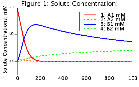
The choices producing this diagram include no flow, two solutes. a linear conversion of A to B in the second compartment, and T1T2 facilitated transport. Solute A is initialized to 1 mM in the first compartment (A1(0) = 1 mM). A is transported from V1 to V2 by a transporter that can bind to either A or B. The transporter can flip from side to side in the unbound form T, or in the bound forms, TA and TB. In V2, A is converted to B by a linear reaction process.
Note that B in compartment one (B1) is greater than B in compartment 2 (B2) where B is produced. B has been transported against a gradient, from low concentration to high concentration.
Description
    TransComp2 is a general model for transporter between two compartments. The
model has five basic choice options:

FLOW
    (1) YES: The model has a flow in compartment 1.
    (2) NO:  The model has no flow.
SOLUTES
    (1) A only:  The model has only one solute, A.
    (2) A and B: The model has  two solutes, A and B.
CONVERT
    (1) None:        There is no conversion of A2 into B2.
    (2) G2aTOb:      If there are two solutes, the loss from A2
                     and gain to B2 is a linear process given
                     by G2aTOb/V2*A2.
    (3) GmaxA2,KmA2: If there are two solutes, the loss from A2
                     and gain to B2 is a Michaelis-Menten process
                     given by
                               GmaxA2*A2/(V2*(1+A2/KmA2)).
TRANSPORTER
    (1) PSa,PSb, Passive: The transport is by a passive process.
                          A1 change = PSa/V1*(A2-A1).
                          A2 change = PSa/V2*(A1-A2).
                          B1 change = PSb/V1*(B2-B1).
                          B2 change = PSb/V2*(B1-B2).
    (2) PSmaxA1, TKmA1 MM A1 1-SIDED: The transport of A1 and A2 is a
           Michaelis-Menten process governed by only the A1 concentration.
                          A1 change = (PSmaxA1/V1)/(1 + A1/TKmA1)*(A2-A1).
                          A2 change = (PSmaxA1/V2)/(1 + A1/TKmA1)*(A1-A2).
    (3) PSmaxA2, TKmA2 MM A1 A2 2 1-SIDED: The transport of A1 and A2 are
           Michaelis-Menten processes where each side has a 1-sided transporter
           for A1 and A2.
                          A1 change = (PSmaxA2/V1)/(1 + A2/TKmA2)*(A2   )+
                                      (PSmaxA1/V1)/(1 + A1/TKmA1)*(  -A1).
                          A2 change = (PSmaxA2/V2)/(1 + A2/TKmA2)*(  -A2)+
                                      (PSmaxA1/V2)/(1 + A1/TKmA1)*(A1   ).
    (4) PSmaxA, TKmA MM A1 A2 2-SIDED: The transport of A1 and A2 is a
          Michaelis-Menten process where the transporter is 2-sided:
                          A1 change = (PSmaxA/V1)/(1 + (A1+A2)/TKmA)*(A2-A1).
                          A2 change = (PSmaxA/V2)/(1 + (A1+A2)/TKmA)*(A1-A2).
    (5) PSmaxAB, TKmAB MM A&B 2-SIDED: The transport of A and B is  governed
          by a single Michaelis-Menten process where the transporter is dependent
          on all four species:
                          A1 change = (PSmaxAB/V1)/(1 + (A1+A2+B1+B2)/TKmAB)*(A2-A1).
                          A2 change = (PSmaxAB/V2)/(1 + (A1+A2+B1+B2)/TKmAB)*(A1-A2).
                          B1 change = (PSmaxAB/V1)/(1 + (A1+A2+B1+B2)/TKmAB)*(B2-B1).
                          B2 change = (PSmaxAB/V2)/(1 + (A1+A2+B1+B2)/TKmAB)*(B1-B2).
    (6) T1&T2, facilitated: A free transporter T flips between side 1 and side 2. (T1<->T2)
        For solute = A only, the change in concentrations are
                          A1 change = SoV1*(koffA1*TA1 - konA1*A1*T1).
                          A2 change = SoV2*(koffA2*TA2 - konA2*A2*T2).
                          T1 change = (koffA1*TA1-konA1*A1*T1)  - kT12*T1   + kT21*T2;
                          TA1 change= (konA1*A1*T1 - koffA1*TA1 - kTA12*TA1 + kTA21*TA2) ;
                          TA2 change=(konA2*A2*T2 - koffA2*TA2 + kTA12*TA1 - kTA21*TA2) ;
                          T2  change = Ttot - TA1 - TA2  - T1.
        For solute = A and B, The equations for A1, A2, TA1, and TA2 are unchanged. The
        equations for T1 and T2 are changed and equations for B1, B2, TB1, and TB2 are added:
                          T1 change = (koffA1*TA1-konA1*A1*T1)  - kT12*T1   + kT21*T2
                                     +(koffB1*Tb1-konB1*B1*T1);
                          T2 change = Ttot - TA1 - TA2 - TB1 -TB2 - T1.

                          B1 change = SoV1*(koffB1*TB1 - konB1*B1*T1).
                          B2 change = SoV2*(koffB2*TB2 - konB2*B2*T2).
                          TB1 change= (konB1*B1*T1 - koffB1*TB1 - kTB12*TB1 + kTB21*TB2) ;
                          TB2 change= (konB2*B2*T2 - koffB2*TB2 + kTB12*TB1 - kTB21*TB2) ;
STAT_FlowYes: STATISTICS: FLOW must be YES for this calculation to be performed.
    (1) A only            Cin = Ain, Cout = Aout.
    (2) B only            Cin = Bin, Cout = Bout.
    (3) A and B           Cin = Ain+Bin, Cout = Aout+Bout;
    The area, mean transit time and relative dispersion are calculated for Cin and Cout.
    In addition, the system transit time and relative dispersion are calculated.

   WARNING: An additional thermodynamic constraint is not included in the model.
   For a passive transporter, the transport rate constants should satisfy
   the following constraints:

   kTA12*kT21*konA1*koffA2
   ------------------------ = 1    (1)  see TestA
   kTA21*kT12*koffA1*konA2

   kTB12*kT21*konB1*koffB2
   ------------------------ = 1    (2)  see TestB
   kTB21*kT12*koffB1*konB2

   These constraints ensure that the model runs to equlibrium at steady-state.
   If these ratios deviate from 1, the model will run to a steady-state
   net concentration gradient.  This would be the case if the transporter
   is coupled to a energy source, which is not explicitly modeled here.
Equations
Not displayed here.
The equations for this model may be viewed by running the JSim model applet and clicking on the Source tab at the bottom left of JSim's Run Time graphical user interface. The equations are written in JSim's Mathematical Modeling Language (MML). See the Introduction to MML and the MML Reference Manual. Additional documentation for MML can be found by using the search option at the Physiome home page.
- Download JSim model MML code (text):
- Download translated SBML version of model (if available):
We welcome comments and feedback for this model. Please use the button below to send comments:
 Klingenberg M. Membrane protein oligomeric structure and transport function. Nature 290: 449-454, 1981.

 Stein WD. The Movement of Molecules across Cell Membranes. New York: Academic Press, 1967.

 Stein WD. Transport and Diffusion across Cell Membranes. Orlando, Florida: Academic Press Inc., 1986.

 Wilbrandt W and Rosenberg T. The concept of carrier transport and its corollaries in pharmacology.
 Pharmacol Rev 13: 109-183, 1961.

 Schwartz LM, Bukowski TR, Ploger JD, and Bassingthwaighte JB. Endothelial adenosin transporter characterization
 in perfused guinea pig hearts. Am J Physiol Heart Circ Physiol 279: H1502-H1511, 2000.

 Foster DM and Jacquez JA. An analysis of the adequacy of the asymmetric carrier model for sugar transport.
 Biochim Biophys Acta 436: 210-221, 1976.
Please cite https://www.imagwiki.nibib.nih.gov/physiome in any publication for which this software is used and send one reprint to the address given below:
The National Simulation Resource, Director J. B. Bassingthwaighte, Department of Bioengineering, University of Washington, Seattle WA 98195-5061.
Model development and archiving support at https://www.imagwiki.nibib.nih.gov/physiome provided by the following grants: NIH U01HL122199 Analyzing the Cardiac Power Grid, 09/15/2015 - 05/31/2020, NIH/NIBIB BE08407 Software Integration, JSim and SBW 6/1/09-5/31/13; NIH/NHLBI T15 HL88516-01 Modeling for Heart, Lung and Blood: From Cell to Organ, 4/1/07-3/31/11; NSF BES-0506477 Adaptive Multi-Scale Model Simulation, 8/15/05-7/31/08; NIH/NHLBI R01 HL073598 Core 3: 3D Imaging and Computer Modeling of the Respiratory Tract, 9/1/04-8/31/09; as well as prior support from NIH/NCRR P41 RR01243 Simulation Resource in Circulatory Mass Transport and Exchange, 12/1/1980-11/30/01 and NIH/NIBIB R01 EB001973 JSim: A Simulation Analysis Platform, 3/1/02-2/28/07.